


|
|
||
|
This part of the tutorial will allow us to revisit the fan control system that we have developed previously.
As a matter of reminder and to help with visual presentation, here is the state transition diagram for our first prototype:
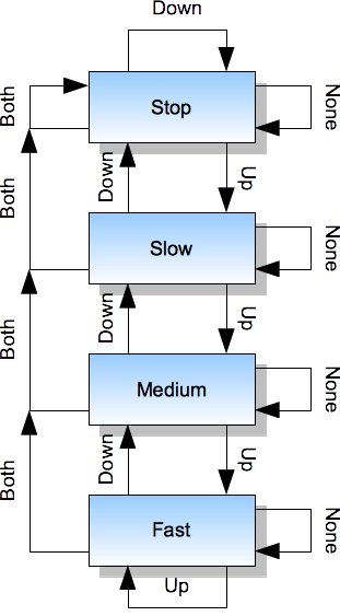
This transition diagram is quite readable and has one interesting visual property: it uses different graphical symbols for states and for inputs, which helps in keeping them conceptually separate: states represent the internal property of the system, whereas inputs come from the external world.
This state transition logic can be also described in the form of a table:
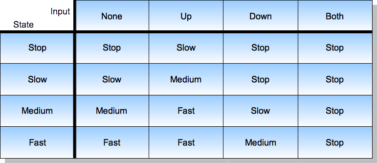
As you see, the information is preserved in the sense that there is a 1:1 mapping between the diagram and the table, although they have different accents. The advantage of tables is that they can be easier to prepare and process - note that such a table is a matrix (also known as a spreadsheet), so there are more tools that are already established and can be reused when working with this form of information.
We can of course implement this state transition table in the same way as before, by expressing all transitions directly in code, but we can also try to retain its form and define an appropriate 2-dimensional array to represent it in code. We can start with the type definitions that we already had before:
   type Fan_State is (Stop, Slow, Medium, Fast);

   type Buttons_State is (None, Up, Down, Both);
and we can define the array type that will have the capability to store the whole transition table:
type Transition_Table is array (Fan_State, Buttons_State) of Fan_State;
The above definition tells us that:
Fan_State - that is, every value of this type can be used as an index value and there will be enough memory allocated to make it possible,Buttons_State,Fan_State, so the array represents the function that for every possible pair [state, input] can show us the target transition state.Note also that there are 4x4 cells in this 2-dimensional array and it should not be confused with an "array of arrays" (as would be the solution in a C programming language) or with a single array of 16 elements, even though we can expect that in memory it will look like one - we will verify that later on.
We can now create a constant and fully initialized value of this type like this:
Transitions : constant Transition_Table :=
   (Stop =>
       (None => Stop,   Up => Slow,   Down => Stop,   Both => Stop),
    Slow =>
       (None => Slow,   Up => Medium, Down => Stop,   Both => Stop),
    Medium =>
       (None => Medium, Up => Fast,   Down => Slow,   Both => Stop),
    Fast =>
       (None => Fast,   Up => Fast,   Down => Medium, Both => Stop));
The above is an aggregate with named value associations, which is a very readable and robust way of initializing arrays. This can be written shortly as:
   Transitions : constant Transition_Table :=
      (Stop   => (Stop,   Slow,   Stop,   Stop),
       Slow   => (Slow,   Medium, Stop,   Stop),
       Medium => (Medium, Fast,   Slow,   Stop),
       Fast   => (Fast,   Fast,   Medium, Stop));
or even shorter as:
   Transitions : constant Transition_Table :=
      ((Stop,   Slow,   Stop,   Stop),
       (Slow,   Medium, Stop,   Stop),
       (Medium, Fast,   Slow,   Stop),
       (Fast,   Fast,   Medium, Stop));
and this can seem attractive as it almost directly maps to the transition table above, but such shorter forms are not protected against reordering of enumeration values in definitions of Fan_State and Buttons_State - for the sake of promoting good programming practice we will prefer the longer form whenever it is reasonable. It certainly makes sense for arrays that are indexed by enumeration values, as each place in the array has a meaningful name.
The Transitions object above is a constant value and as we have explored in the previous chapter, this value will end up in the flash address space after linking, if we define it at the package level (preferably in the package body). This is perfectly OK, as we will not need to modify it.
We can now rewrite our Run procedure (Control_Motor and Read_Buttons can stay without any changes) like this:
   procedure Run is
      Current_State : Fan_State;
      Buttons : Buttons_State;
   begin

      -- initialize the device
      -- ... as before

      -- repeat the control loop
      loop
         Read_Buttons (Buttons);

         Current_State := Transitions (Current_State, Buttons);

         Control_Motor (Current_State);

         Utils.Waste_Some_Time;
      end loop;
   end Run;
Note again the most important part of this rewritten procedure:
Current_State := Transitions (Current_State, Buttons);
This single line replaces 45 lines of code from the previous version at the expense of one additional constant array that defines all transition rules in one place. Interestingly, accessing array content this way looks like a function call and in fact it would look the same if we refactored the transition rules to a separate function instead of using an array.
This approach has some additional advantages:
Run procedure - as such, the operational rules are decoupled from the source code, which makes both of them more reusable in separation,Transitions object (our implementation-level artefact), which means that it is easy to verify and the possibilities for introducing errors are very small,On the other hand, debugging our new version in a step-wise manner can be less intuitive, as the source code alone does not fully describe the operation of the final device.
In other words, the set of advantages and disadvantages is entirely reversed when compared to our first version, so it is a matter of engineering judgment which variant is preferred in any given context.
To complete this chapter we should still verify our assumptions related to how the transition table is placed in the flash memory. After successful compilation, linking and transformation to the raw binary image we can check that the Transitions object was placed at address 0x80cc8 (note that depending on how the linker is invoked and what are the memory boundaries defined for each target device, the symbol order and their addresses can be different):
$ nm program.elf
...
00080cc8 r program__transitions
...
and that the binary image, at the offset of 0xcc8, contains these values (here reformatted for 4x4 byte output):
00 01 00 00
01 02 00 00
02 03 01 00
03 03 02 00
Can you recognize this pattern? It corresponds to the content of the Transitions object, and also indicates that the compiler has chosen to represent the Fan_State type with just one byte and that the individual enumeration values have representations starting from 0. These details are not very useful for us (we will not exploit them), but it is interesting to note that the Ada compiler by default selected the smallest representation that was reasonably possible without jeopardizing access times.
Previous: Constant Values, next: Machine Code Insertions.
See also Table of Contents.