


|
|
||
|
In the previous chapter we have used a simple linker script to instruct the linker how to prepare the executable file from our compiled program elements.
This script is very simple, but in order to understand it we need to have a look into the microcontroller documentation.
The memory layout of the microcontroller is explained in section Product Mapping of the Atmel documentation or in section Memory Mapping of the STM32 documentation. The parts that are of interest to us differ between different microcontrollers.
Arduino M0
We can see from the Product Mapping section that the Internal Flash memory is located at the beginning of the memory space, which is 0x00000000. On the other hand, the sections about Memory Controller and Memory Organization mention the ability of the chip to protect some initial area of the flash for the purpose of the bootloader.
The size of the protected area is configurable, but Arduino M0 boards are already configured for the 16kB bootloader, meaning that the unprotected area of flash begins at address 0x00004000. This means that our programs should be written with this offset in mind, but we do not need to prepare images that have "empty space" at the beginning in order to fit that starting address. Our binaries should be prepared as if there was nothing else before that starting address and this is also where they will be flashed.
We can assume that the microcontroller, together with the bootloader that is already installed in it, will arrange for our program to start from that address after reset or power on.
Another value that is of interest to us from the Product Mapping is the extent of the SRAM memory, where the program will store its run-time data. This memory block has 32kB, starting from 0x20000000, which means that the last address in SRAM is 0x20007fff.
Arduino Zero
The notes about Arduino M0 apply here as well, with the exception of the bootloader size - in the Zero board the protected memory area has 8kB and this is why the value 0x00002000 is the offset that is provided to the openocd tool in order to instruct it where the file should be uploaded.
Arduino Due
We can see from the Product Mapping section that the layout of memory, in a slightly simplified version, looks like in the following diagram:
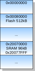
Note how the beginning of the address space is partitioned and how the internal flash memory is mapped in the whole address space: the flash memory starts at address 0x00080000 and has a span of 512kB. The starting address is important here - anything that we upload to the flash memory will be visible at that address range - that is, the first byte of our binary images will be placed at address 0x00080000, the second byte at address 0x00080001, and so on. We do not need to prepare images that have "empty space" at the beginning in order to fit that starting address.
The board is able to boot in two modes: the bootloader mode that is used to upload new programs to the flash memory (this mode can be entered after pressing ERASE button and then RESET button) and the flash mode that is established by bootloader (to be exact, bossac sends the instruction to the bootloader to do it) after new program is loaded. This is convenient and from the microcontroller point of view differs only in which address is considered the starting one - in the bootloader mode it is the 0x0 address (and as you can see on the diagram in the documentation, the boot memory is located there) and in the flash mode the beginning of the flash memory is visible there instead, as explained in more detail below. In other words, once the program is loaded, each subsequent reboot will cause the board to effectively start from address 0x00080000 - this is where we put our binary images.
Another value that is of interest to us from the Product Mapping is the extent of the SRAM memory, where the program will store its run-time data. This memory has 96kB, visible in a continuous range from 0x20070000 to 0x20087fff.
STM32 Nucleo-32
We can see from the Memory Mapping section in the datasheet that the layout of memory, in a slightly simplified version, looks like in Arduino Due, but with different address ranges:
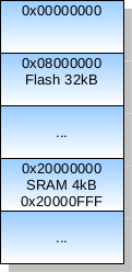
The beginning of the address space is partitioned and the internal flash memory is mapped: the flash memory starts at address 0x08000000 and has a span of 32kB. The starting address is important here - anything that we upload to the flash memory will be visible at that address range - that is, the first byte of our binary images will be placed at address 0x08000000, the second byte at address 0x08000001, and so on. We do not need to prepare images that have "empty space" at the beginning in order to fit that starting address, but we will instruct the loader with appropriate loading offset to place our binaries in the correct location.
Similarly to Arduino Due, the Nucleo-32 board is able to boot in several different modes. One of these modes ensures that the flash memory range is aliased at address 0x0, where the processor expect to find the beginning of the vector table (see below for more details on this). In other words, once the program is loaded, each subsequent reboot will cause the board to effectively start from address 0x08000000 - this is where we put our binary images.
Another value that is of interest to us from the Memory Mapping is the extent of the SRAM memory, where the program will store its run-time data. This memory has only 4kB and is visible in the address range from 0x20000000 to 0x20000fff.
STM32 Nucleo-144
We can see from the Memory Mapping section in the datasheet that the layout of memory, in a slightly simplified version, looks like in Arduino Due, but with different address ranges:
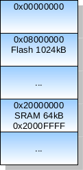
The beginning of the address space is partitioned and the internal flash memory is mapped: the flash memory starts at address 0x08000000 and has a span of 1024kB. The starting address is important here - anything that we upload to the flash memory will be visible at that address range - that is, the first byte of our binary images will be placed at address 0x08000000, the second byte at address 0x08000001, and so on. We do not need to prepare images that have "empty space" at the beginning in order to fit that starting address, but we will instruct the loader with appropriate loading offset to place our binaries in the correct location.
Similarly to Arduino Due and Nucleo-32, the Nucleo-144 board is able to boot in several different modes. One of these modes ensures that the flash memory range is aliased at address 0x0, where the processor expect to find the beginning of the vector table (see below for more details on this). In other words, once the program is loaded, each subsequent reboot will cause the board to effectively start from address 0x08000000 - this is where we put our binary images.
Another value that is of interest to us from the Memory Mapping is the extent of the SRAM memory, where the program will store its run-time data. The Nucleo-144 board has several regions of SRAM that together form a continuous address range, but these regions are accessed on different buses and have different access times. We can see that the first 64kB block of memory is described as intended for "critical real-time data" and for the sake of simplicity we can decide to use only that block, as it is definitely big enough for our purposes. This memory is visible in the address range from 0x20000000 to 0x2000ffff.
The documentation for each microcontroller (and the ARM documentation in general) describes the so-called vector table, which is an array containing several important addresses. The ones that are of interest to us at the moment are at the bottom (beginning) of the table:
Run procedure (visible to the linker as symbol run) to be the first that is called when the program starts; this address should be put as the second word of the vector table.The expected top of stack value deserves a bit of explanation. The program uses the stack space to store local variables and to manage the whole function call and return mechanics. The stack is allocated towards lower addresses, starting from the top-of-stack address. When there is a need to store some value on the stack, the processor pushes that value by decreasing the so-called stack pointer and then by storing the value in the newly computed location. For example, if the stack pointer has the value 0x20001000, then pushing a 32-bit word to the stack is performed by decreasing the stack pointer by 4 bytes (so the new stack pointer value will be 0x20000ffc) and then storing the 32-bit word at that location (so the value will occupy 4 bytes at addresses 0x20000ffc, 0x20000ffd, 0x20000ffe and 0x20000fff). Similarly, further words will be pushed at lower addresses. Thus, top-of-stack address 0x20001000 is appropriate if we want to locate the stack at the end of available memory that extends up to 0x20000fff.
Note that it is not necessary to locate the stack at the end of available SRAM memory and in some systems it might make sense to locate it somewhere else or to even manage multiple stacks for isolated parts of the system. In simple setups, however, it is common and reasonable to allocate the stack space at the end of available memory and therefore give it maximum capacity for growth towards the beginning of SRAM (that it, towards lower addresses), where the program might want to allocate other objects like static variables.
Note also that the least-significant bit of each program counter value should be 1 to indicate the appropriate (Thumb) instruction set. This is a property of all ARM Cortex-M controllers.
The vector table should start at the beginning of the address space and so should be placed at the beginning of the binary image that we want to upload to the flash memory.
The vector table defines some more slots, but we will not need them at the moment. The extent of the whole table depends on the target microcontroller - or to be more exact, on the number of different interrupts that the microcontroller is able to handle. This can be found in chapters devoted to interrupts and exception vectors. For Arduino and Nucleo-32 boards we can generously assume that the whole range from 0x00 to 0xFF is reserved for vector table, but the microcontroller used in Nucleo-144 is more capable with regard to interrupt handling and we will reserve the range 0x00 to 0x1FF for the vector table. In any case, the whole table should be mostly zeroed except for the first two slots, as described already. We can use the remaining memory (that is, from 0x100 or 0x200 upwards, counting from the beginning of the binary image) for other needs, like our program's code and data. In our first program the only thing that we really need apart from the vector table is the executable code for the Run procedure.
In summary, we need to prepare the binary image that will contain, from the beginning:
Run procedure (seen as run here),Run procedure.
The linker script (stored in file flash.ld) that knows how to prepare the image according to these requirements will be different depending on the target device.
Arduino M0
The linker script for Arduino M0 is (note 0x00004000 as the offset in the flash memory to account for the protected bootloader and 0x20008000 as the top-of-stack value, which is past-the-end address in SRAM):
OUTPUT_FORMAT("elf32-littlearm")
OUTPUT_ARCH(arm)

SECTIONS
{
    .vectors 0x00004000 :
    {
        LONG(0x20008000)
        LONG(run + 1)
        FILL(0)
    }

    .text 0x00004100 :
    {
        *(.text)
    }
}
Arduino Zero
The linker script for Arduino Zero is (note 0x00002000 as the offset in the flash memory to account for the protected bootloader and 0x20008000 as the top-of-stack value, which is past-the-end address in SRAM):
OUTPUT_FORMAT("elf32-littlearm")
OUTPUT_ARCH(arm)

SECTIONS
{
    .vectors 0x00002000 :
    {
        LONG(0x20008000)
        LONG(run + 1)
        FILL(0)
    }

    .text 0x00002100 :
    {
        *(.text)
    }
}
Arduino Due
The linker script for Arduino Due is (note 0x00080000 as the beginning of the flash memory and 0x20088000 as the top-of-stack value, which is past-the-end address in SRAM):
OUTPUT_FORMAT("elf32-littlearm")
OUTPUT_ARCH(arm)

SECTIONS
{
    .vectors 0x00080000 :
    {
        LONG(0x20088000)
        LONG(run + 1)
        FILL(0)
    }

    .text 0x00080100 :
    {
        *(.text)
    }
}
STM32 Nucleo-32
The linker script for Nucleo-32 is (note 0x08000000 as the beginning of the flash memory and 0x20001000 as the top-of-stack value, which is past-the-end address in SRAM):
OUTPUT_FORMAT("elf32-littlearm")
OUTPUT_ARCH(arm)

SECTIONS
{
    .vectors 0x08000000 :
    {
        LONG(0x20001000)
        LONG(run + 1)
        FILL(0)
    }

    .text 0x08000100 :
    {
        *(.text)
    }
}
STM32 Nucleo-144
The linker script for Nucleo-144 is (note 0x08000000 as the beginning of the flash memory and 0x20010000 as the top-of-stack value, which is past-the-end address in SRAM; note also that we have reserved 0x200 bytes for the vector table, which is twice as much as in the smaller boards):
OUTPUT_FORMAT("elf32-littlearm")
OUTPUT_ARCH(arm)

SECTIONS
{
    .vectors 0x08000000 :
    {
        LONG(0x20010000)
        LONG(run + 1)
        FILL(0)
    }

    .text 0x08000200 :
    {
        *(.text)
    }
}
As you can see, the above are very simple scripts that instruct the linker to do exactly what we need. There are two "blocks" or sections in the final binary layout - one called .vectors and one called .text. The first section contains the top of stack value followed by the value of the run symbol (this is the address of our Run procedure), incremented by 1 to select the Thumb instruction set, filled with zeros up to the second section, which starts at offset 0x100 or 0x200 from the beginning of the image. That second section will simply contain anything that was marked as .text after compiling our program and you can check the assembly output from the previous chapter that our run symbol was placed in a section called .text as well.
We can review again the invocation of the linker:
$ ld -T flash.ld -o program.elf program.o
The linker is instructed to use our script flash.ld to drive its work, use the script appropriate for the target chip.
The list of symbols is now clear as well (here shown for Arduino M0):
$ nm program.elf
0000410c D program_E
00004100 T run
As you see, the Run procedure (known to the linker as run) got assigned 0x00002100 as a starting address and thanks to this, the linker also knew what to put in the second slot of the vector table.
We can again create the raw binary image:
$ objcopy -O binary program.elf program.bin
and inspect it with object dump.
Assuming Arduino M0 as the target, the complete dump of our binary executable is:
$ od -A x -v -t x4 program.bin
000000 20008000 00004101 00000000 00000000
000010 00000000 00000000 00000000 00000000
000020 00000000 00000000 00000000 00000000
000030 00000000 00000000 00000000 00000000
000040 00000000 00000000 00000000 00000000
000050 00000000 00000000 00000000 00000000
000060 00000000 00000000 00000000 00000000
000070 00000000 00000000 00000000 00000000
000080 00000000 00000000 00000000 00000000
000090 00000000 00000000 00000000 00000000
0000a0 00000000 00000000 00000000 00000000
0000b0 00000000 00000000 00000000 00000000
0000c0 00000000 00000000 00000000 00000000
0000d0 00000000 00000000 00000000 00000000
0000e0 00000000 00000000 00000000 00000000
0000f0 00000000 00000000 00000000 00000000
000100 af00b580 46c046c0 46c0e7fc 00000000
00010d
The first two words (top of stack and program start) are essential and you should be able to recognize them from the content of the linker script. These values will be of course different for other boards, which have different memory layouts and therefore different top-of-stack and program starting points.
You should be able to see that the vector table was indeed placed at the beginning of the binary image and that several non-zero values - presumably the instruction codes from our Run procedure - begin at offset 0x100, which is exactly what was intended.
The program is loaded to the flash memory at the appropriate location, but what happens when the board is reset or powered on will differ between boards.
Arduino M0
The Arduino M0 uses a very simple microcontroller, which has a fixed memory layout, where program code (with the vector table) starts from 0x0. The chip used in the board has the bootloader already installed, which allows to either upload new programs to the flash memory via the USB port, or to pass the control to the actual user program. The memory occupied by the bootloader is protected against writing and this is the reason why our own programs are flashed to the memory space starting from 0x00004000 instead of 0x0. When the board is reset for normal execution, the bootloader instructs the microcontroller that the vector table is located at the offset address and passes control to the user program.
It is possible to reconfigure the chip to unlock the protected range of memory and then upload user programs from the very beginning of the address space, but after doing so the board would need to have its bootloader reprogrammed in order to be useable again with the Arduino IDE. By leaving the original Arduino bootloader intact and placing our own programs at the location where it is expected (that is, at offset 0x00004000), we can retain the original functions of the board.
Arduino Due
Things look a bit differently with Arduino Due, which has a hard-programmed bootloader and the internal flash memory starting from address other than 0x0 and which uses address aliasing to achieve flexible startup functionality.
The program image will be loaded at the beginning of the flash memory, which starts at 0x00080000, so the Run procedure will in fact have its first instruction at 0x00080100, which agrees with the second slot of the vector table. This is exactly what we have configured in the linker script.
Just to make all this information a bit easier to digest, the following diagram presents the layout of our binary image in the address space:
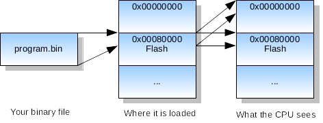
As you see, the content of the program.bin image file is loaded into the flash block of memory starting at 0x00080000, but then, thanks to the special controlling register that is set by bossac after the image is loaded, each subsequent reboot will cause the initial region of memory to be aliased or mirrored from the flash memory (that is, the same content will be visible in two address regions) and this is what allows the processor to properly find and match everything. These two facts are important:
The above facts are consistent and allow the processor to properly execute the Run procedure after reset.
STM32 Nucleo-32 and Nucleo-144
The booting process can be explained in similar terms to Arduino Due, as Nucleo-32/144 also uses address aliasing to achieve flexible startup functionality.
The program image will be loaded at the beginning of the flash memory, which starts at 0x08000000, so the Run procedure will in fact have its first instruction at 0x08000100 (or 0x08000200 in the case of Nucleo-144), which agrees with the second slot of the vector table. This is exactly what we have configured in the linker script.
Just to make all this information a bit easier to digest, the following diagram presents the layout of our binary image in the address space:

As you see, the content of the program.bin image file is loaded into the flash block of memory starting at 0x08000000, but then, thanks to the special controlling register that is set automatically after the image is loaded, each subsequent reboot will cause the initial region of memory to be aliased or mirrored from the flash memory (that is, the same content will be visible in two address regions) and this is what allows the processor to properly find and match everything. These two facts are important:
The above facts are consistent and allow the processor to properly execute the Run procedure after reset.
In any case, you have seen that the linker script, even as simple as the ones we have used, is a powerful tool that allows us to prepare binary images exactly as expected by hardware.
We will extend the linker script with additional elements when they are needed.
Previous: First Program, next: Digital Output.
See also Table of Contents.